
The guide
A picture has no thickness, so turning one into a solid means deciding where the edge is
There are two honest ways to give a flat image a third dimension: trace its outline, or read its brightness as height. They suit different pictures and fail differently.
- 0.42 mm thinnest safe line for a 0.4 mm nozzle, by one slicer's manual
- n - 2 triangles in any triangulation of a polygon with n corners
- 29,750 triangles in a 120 by 120 sample relief
- 10 days length of one study's wash test on printed cups that held milk
- 1935/2004 the EU regulation for anything that touches food
Read the full guide Fold the guide
A picture is a grid of colored squares. A printed part is a volume with an inside and an outside. Nothing in the picture says where the plastic should be, so every converter has to invent that answer, and the two usual inventions have almost nothing in common.
The first reads the picture as a shape. Somewhere between the dark ink and the light paper there is an edge; find it, follow it all the way round, and you have an outline that can be pushed up into a slab, raised on a plate, or wrapped in a wall. The second reads the picture as terrain. Each pixel’s brightness becomes a height, and the result is a small landscape with a flat floor under it.
Choosing between them is the whole craft. The rest is cleanup.
Shapes: finding an edge that was never drawn
Tracing starts by forcing every pixel to take a side. Thresholding is the simplest way to separate an object from its background: pick one brightness, call everything darker “shape” and everything lighter “not”. The brightness itself is a weighted sum of the three color channels; a common library uses 299 parts red, 587 green and 114 blue in a thousand, which is why a saturated green logo reads far lighter than a blue one.
One global threshold works when the background is even. It fails on a phone photo of a sketch, where the paper is bright near the window and gray in the far corner, and the documentation for image libraries is frank that a varying background wants a local threshold instead. A flat scan or a clean export avoids the problem entirely. That is the cheapest improvement available: fix the picture before fixing the trace.
What survives the threshold is rarely clean. Dust becomes islands, and gaps in a pen stroke become lakes. The standard repairs come from mathematical morphology: an opening removes small bright spots, a closing removes small dark ones. Deleting every island and filling every lake below a chosen area does the same job more bluntly, and a slight blur before the threshold calms the fringe of a ragged edge.
Then comes the outline itself. The paper behind one widely used tracer puts the difficulty plainly: tracing cannot generate information that is not already present, many different outlines could have produced the same bitmap, and drawing each pixel as a precise square gives a staircase nobody intended. A good tracer has to decide which features are real and which are artifacts of scanning.
There is also a small question of honesty at the corners. Where two dark pixels touch only diagonally, an outline following the pixel edges reaches a crossing and must turn one way or the other. That paper lists seven policies for the choice. None is correct. Each simply decides whether a diagonal hairline stays one piece or falls into beads. A method that walks between pixel centers instead, placing each point on the line between a dark pixel and a light neighbor, sidesteps the crossing: the contour cuts the corner and can never touch itself.
The raw contour has a point for every pixel step, far more than a printer can express. The usual thinning method keeps the two ends of a run, finds the point farthest from the straight line between them, and keeps that point too if it is farther than a tolerance; otherwise everything in between goes. It is fast and predictable, with one catch that a mapping database’s manual spells out: the simplified result may no longer be a valid polygon. Two outlines that were a pixel apart can cross once each has been straightened. Any tool that builds solids from the result has to check and back off.
From outline to solid
An outline with holes becomes a slab by capping it with triangles top and bottom and running a wall around every loop. The capping is the hard part. A polygon with n corners always divides into n - 2 triangles, and the simplest method, ear clipping, repeatedly cuts off a corner whose triangle contains no other corner. Holes are handled by cutting a slit from each hole to the outer boundary so the whole thing becomes one loop.
The file that carries the result is plainer than people expect. An STL is a list of triangles and nothing else, and its rules are few. Corners are listed counterclockwise as seen from outside, and each triangle must share an edge with each neighbor, so no corner may sit in the middle of another triangle’s side. Break that rule and the surface has a seam. The format’s own specification adds that it carries no scale: the numbers are arbitrary units, and millimeters are only a habit that slicing programs share.
A stamp is a slab with a second, smaller slab on top, and it has one trap. The raised parts carry the ink, exactly as in a woodcut, where what is cut away stays clean and what is left at the surface prints. Press a face onto paper and left and right change places. So the shape on the stamp must be built backwards for the mark to read forwards. This needs no authority; fold a sheet over wet ink and look. A preview of the impression is worth more than a rule, because the mistake costs a whole print to discover.
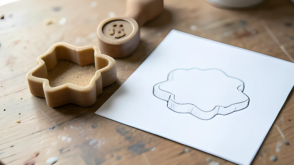
A cookie cutter is an outline that has been given thickness outward. Offsetting a polygon sounds trivial and is not: at every outside corner something has to fill the wedge. One polygon library’s documentation describes the choices. A round join sweeps an arc whose radius is the offset distance. A mitered join extends the edges to a point and needs a limit, or a sharp corner grows a long spike. Rounded is the right choice for a cutter, since the wall then has the same thickness everywhere.
I could not find a standards body or university page that gives proportions for a cutter’s wall, edge or flange, so none are quoted here. The numbers a design tool starts with are starting points. What can be said is structural: a thin edge cuts dough cleanly, a thicker wall keeps the shape from flexing, and a wide flange gives the palm something to press.
Terrain: brightness as height
The relief asks nothing of the picture except that bright and dark mean something. Sample the brightness on a grid, lift each sample by its value, add a base, close the sides. There is no edge to find and so no trace to go wrong.
It suits photographs of texture, maps, coins, anything with gradual tone. It suits logos badly. A hard edge between black and white becomes a cliff one sample wide, the cliff inherits the staircase of the grid, and no amount of resolution turns it into a clean wall. A logo wants tracing; a fabric swatch wants relief.
Resolution costs triangles at a quadratic rate. A grid of 120 by 120 samples needs 2 x 119 x 119 triangles for the top, plus walls and floor: 29,750 in the tool on this page. Double the samples and the count roughly quadruples, while the printer, laying a bead of plastic, shows none of the difference.
What the nozzle will not draw
Every design on screen is finer than the machine. The manual of one open source slicer names the floor. For the outermost loop of a part it defaults to a line 1.05 times as wide as the nozzle, which it calls the thinnest safe extrusion width. For a 0.4 mm nozzle that is 0.42 mm. Neighboring lines overlap a little, so at a layer height of 0.2 mm two of them make a wall about 0.8 mm thick, and the manual recommends at least two.
The settings file of a second slicer agrees and goes further. A line of plastic is generally as wide as the nozzle, 0.4 mm by default, and the default wall is 0.8 mm, two lines side by side. Anything under the minimum feature size, a quarter of a line width, is not printed at all, and anything a little wider is thickened to the minimum wall line, 85 percent of the nozzle. One consequence is plain arithmetic: a pin or rib narrower than 1.6 mm, two such walls back to back, is all wall with nothing inside.
For a traced shape this means hairlines and serifs can vanish between the screen and the bed. The fix is arithmetic: a stroke two pixels wide in a 600 pixel picture, printed 60 mm across, is 0.2 mm. A distance transform, which measures how far each pixel sits from the nearest background pixel, can mark such strokes before the print.
A worked example ties it together. The star that the tool opens with, set to 60 mm on its longest side and 3 mm thick, comes out 60 by 57.1 by 3 mm. Its outline has 57 points in two loops, the star and a round hole, and the solid has 228 triangles enclosing 4.38 cubic centimeters. The file is about 11 kilobytes. Switch to relief at 120 samples and the same picture needs 29,750 triangles and about 1.4 megabytes, for a part that looks softer and prints slower.
What this cannot promise
A cutter made this way touches food, and the plastic deserves more suspicion than the geometry. One printer maker’s guide warns that a printed part can turn into a culture dish within weeks, because bacteria settle in its small nooks and crannies and a dishwasher does not remove them. It adds that particles can migrate from the parts of the printer itself, so everything the material touches on its way should be food grade too. The nozzle is the obvious case. A brass one is sufficient for soft plastics, so brass is common, and brass often has about 2 percent lead added to make it easier to machine.
A university study put numbers on the washing. Printed cups of two filaments held milk at intervals over ten days and were then washed by hand or in a dishwasher at 70 degrees Celsius. On the hand-washed PETG cups the bacterial count, on a logarithmic scale, rose from 1.28 after the first day to 1.52 after the tenth; on the machine-washed ones it fell from 1.30 to 1.06. The authors call the grooves between layers the greatest risk, since bacteria multiply in spaces too narrow to clean. The hot wash did better than the guide allows, though it also changed the strength of the parts.
The maker’s guide also draws the useful distinction. A food grade material is permitted to touch food; a food safe object is one whose material, shape and use together create no hazard. It adds that coatings do not guarantee safety, since they can degrade and expose what is underneath. In the European Union the test is legal: materials that touch food fall under Regulation (EC) No 1935/2004 and must not release substances that could endanger health.
Tracing also cannot give permission. A logo is someone’s mark, and converting it changes nothing about who may use it.
And no converter recovers detail the picture never held. A small, soft, compressed image traces into a lumpy outline at any setting. The honest remedy is a better picture, large, flat and high in contrast, and then the edge is easy to find because someone already drew it.
Sources
Every source consulted for this guide. Links checked October 4, 2026.
- Potrace: a polygon-based tracing algorithm Peter Selinger, 20 September 2003
- Contour finding - skimage 0.26.0 documentation scikit-image
- Thresholding - skimage 0.26.0 documentation scikit-image
- Morphological Filtering - skimage 0.26.0 documentation scikit-image
- Image module - Pillow (PIL Fork) 12.3.0 documentation Pillow
- ST_Simplify PostGIS manual
- Triangulation by Ear Clipping David Eberly, Geometric Tools, last modified 3 August 2024
- JoinType Clipper2 documentation, Angus Johnson
- Distance Transforms of Sampled Functions P. Felzenszwalb and D. Huttenlocher, Theory of Computing, 2012; project page at Brown University
- STL (STereoLithography) File Format Family Library of Congress, Sustainability of Digital Formats
- The StL Format Fabbers.com, from the StereoLithography Interface Specification
- Cura/resources/definitions/fdmprinter.def.json at main - Ultimaker/Cura - GitHub UltiMaker, Cura source code (LGPL-3.0)
- Slic3r Manual - Flow Math Slic3r Manual (CC BY-SA 3.0)
- Investigating the effect of dishwasher on 3D printed food-contact material G. G. Kailo and others, Progress in Agricultural Engineering Sciences 21 (2025), CC BY 4.0, in the Repository of the Academy's Library
- Fused filament fabrication - Wikipedia Wikipedia
- Brass - Wikipedia Wikipedia
- The Essential Guide to Food Safe 3D Printing | Formlabs Formlabs
- Food Contact Materials - Food Safety - European Commission European Commission
- Woodcut - Wikipedia Wikipedia