The guide
A truss is a promise made by triangles, and counting its bars is not enough to keep it
Why triangles hold their shape, how one joint at a time reveals every force, and why a correct bar count can still describe a structure that folds.
- m + r = 2j the count for a statically determinate plane truss
- 90 kN top chord force at midspan in the worked Pratt example
- 1844 year the Pratt truss was patented
- 0.43 worst Euler buckling ratio in the worked example
Read the full guide Fold the guide
Push down on the middle of a ladder lying across two chairs and it sags. Push down on a bridge made of short bars arranged in triangles and almost nothing visible happens. The difference is not the material. It is the arrangement, and the arrangement has rules that can be counted, drawn and solved by hand.
Why the triangle holds
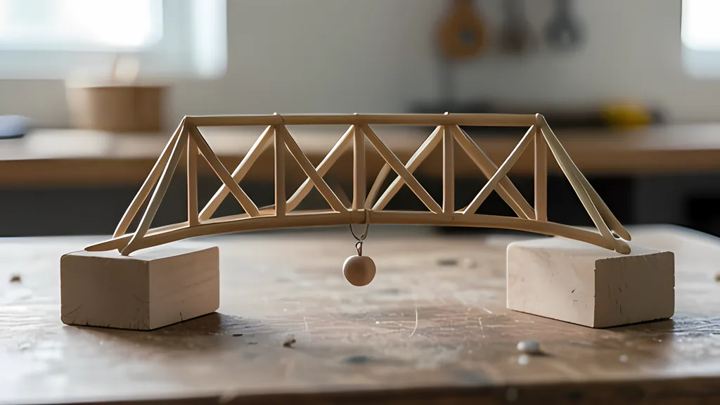
A truss is a structure made entirely of two-force members: bars that are loaded only at their two ends. A body loaded at just two points can only be in equilibrium if the two forces are equal, opposite and collinear, so every bar of a truss is in simple tension or simple compression and nothing else. That one fact is what makes trusses both strong and easy to reason about. There is no bending to calculate, only a single number for each bar.
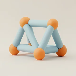
The simplest truss is a single triangle, and the triangle is stable in a way a square is not. Give a square four hinged bars and it will lean into a parallelogram at the first sideways nudge. Give a triangle three hinged bars and the only way to change its shape is to stretch or squash one of them, which the bar resists with an axial force. Build a large structure out of triangles and the whole thing inherits that stubbornness.
Real trusses are not hinged. Their joints are bolted, welded, riveted or nailed through gusset plates. The analysis pretends otherwise, and for good reason. When members are long and slender, the moments carried through the joints are small, so the joints can be treated as pins. When loads are applied only at the joints, the members then carry pure tension or compression. Member weight is usually small next to the applied loads, and when it is not, half of each member’s weight can be hung on each of its two end joints. Those three simplifications, pins, joint loads and lumped self-weight, are the whole idealization, and every number this tool reports rests on them.
The pin was not only a modelling convenience. A National Park Service nomination for a Kansas truss bridge notes that, until the twentieth century, American truss panel points were generally connected with a pin, partly because it was much easier for engineers of the period to calculate the stresses than in a riveted joint.
Counting is necessary, and never enough
For a flat truss with j joints, each joint gives two equations of equilibrium: forces along x and along y must balance. That is 2j equations. The unknowns are the m member forces plus the r reaction components at the supports, where a pin contributes two and a roller one. If m + r equals 2j, the equations and the unknowns match, and the truss is called statically determinate: its forces follow from equilibrium alone, whatever the members are made of.
If m + r is larger, there are more bars than equilibrium can settle, and the truss is statically indeterminate. Its forces then depend on how stiff each member is, because a stiffer bar attracts more load. If m + r is smaller than 2j, the truss is short of bars and cannot be stable. James Clerk Maxwell was already writing on the equilibrium and stiffness of frames in 1864.
Here is the trap. The count is a necessary condition for stability, not a sufficient one. Take two square bays side by side, sharing a vertical. Put both diagonals in the left bay and none in the right. The left bay is overbraced, the right bay can rack like an unbraced bookcase, and yet the total count comes out exactly right: nine members and three reactions against six joints. The surplus bar on one side does nothing to stop the mechanism on the other. A framework can be statically and kinematically indeterminate at once, a situation Pellegrino and Calladine analysed by matrix methods in 1986.
So this tool checks twice. It counts, and it also asks the stiffness equations directly whether any pattern of joint movements exists that stretches no member. If one exists, the truss is reported unstable, the joints that can move are named, and the movement is drawn as a dashed shape. Nothing is solved silently. The queen post template shows the classic case. The Federal Highway Administration’s covered bridge manual notes that a queen post truss with no diagonal in its central rectangular panel is not a true truss at all but a frame, and with pin joints that panel simply sways.
One joint at a time
The method of joints is how students first meet trusses, and it is worth doing by hand at least once. Label the joints with letters. Treat the whole truss as one rigid body and solve for the support reactions from three equations: forces in x, forces in y, and moments. Then find a joint with no more than two unknown member forces, draw its free body, and solve the two equilibrium equations. Draw every unknown as a tension pulling away from the joint; a negative answer simply means compression. Move to the next joint that now has two or fewer unknowns, and repeat.
A worked example makes this concrete, and every number below can be reproduced in the tool on first load. Take a Pratt truss spanning 18 m, 3 m deep, with six panels of 3 m and a load of 20 kN hanging from each of the five interior joints of the bottom chord. The left end is pinned and the right end sits on a roller. By symmetry each support carries half of the 100 kN total, so both reactions are 50 kN upward.
At the left support joint, only two members meet: the bottom chord and the sloping end post, which rises at 45 degrees. Vertical equilibrium gives the end post force times sin 45 degrees plus 50 kN equals zero, so the end post carries 70.71 kN of compression. Horizontal equilibrium then gives the bottom chord 50 kN of tension. Two joints further in, the forces have grown: the top chord at midspan carries 90 kN of compression and the bottom chord beneath it 80 kN of tension. The unloaded vertical at the top of the middle joint carries nothing at all. It is a zero-force member, which the standard joint rules predict and the solution confirms.
The method of sections is the shortcut when only one member is wanted. Cut the truss through no more than three members, keep one side, and take moments about the point where two of the cut members meet. For the top chord at midspan, moments about the bottom joint below it give 50 kN times 9 m, less the loads at 6 m and 3 m from that joint, all divided by the 3 m depth: 90 kN, the same answer.
What the computer does instead
Hand methods depend on finding a joint with two unknowns, and indeterminate trusses have no such starting point. The direct stiffness method avoids the problem entirely. In this tool each bar is described by how much force it takes to stretch it, its modulus times its area divided by its length, turned into the global x and y directions. Those small matrices are added into one large stiffness matrix for the whole truss, the supports remove the restrained displacements, and one linear system gives every joint movement at once. Member forces follow from how far each bar has stretched.
In 1956 Turner, Clough, Martin and Topp published a paper on the stiffness and deflection analysis of complex structures. A 1966 report from the Jet Propulsion Laboratory put the character of the method plainly: it is a matrix procedure meant for digital computers, and by hand it suits only the simplest problems.
The tool solves every truss this way, then solves every determinate truss a second time by the method of joints, which uses no stiffness at all, and compares the two. On the worked example they agree to better than one part in a trillion, and every joint balances. The stiffness solution also gives displacements: with the tool’s typical steel values and 2000 mm2 bars, the middle of the bottom chord drops about 7.2 mm. The drawing exaggerates that sag by a stated factor so the shape can be seen.
Slender bars, old patents, honest limits
Tension and compression are not mirror images. A bar in tension simply stretches until the material yields. A slender bar in compression can fail long before that by buckling sideways. The Wood Handbook gives the classical result for a long, pin-ended column: the critical stress is pi squared times the modulus, divided by the square of the slenderness ratio. Multiplied out for a bar of length L, that is pi squared E I divided by L squared.
In the worked example the 4.24 m end posts are the most slender members in compression. With the tool’s default second moment of area their buckling ratio is 0.43, well clear of 1, while the stress in them is a modest fraction of the steel’s yield strength.
The forms themselves carry history. The Federal Highway Administration records that William Howe received his first truss patent in 1840 and a second later that year, which used metal rods as the verticals of a timber truss, and that he included a detailed structural analysis with his application. The National Park Service nomination dates the basic Pratt truss to a patent of 1844 by Thomas and Caleb Pratt, and the Warren to a patent by two British engineers in 1848.
In the Pratt design the diagonals work in tension and the verticals in compression. Load the tool’s Howe template the same way and the roles swap: diagonals in compression, verticals in tension. The tool builds both, along with Warren, K, king post, queen post, Fink roof and cantilever forms.
Every check on this page is a teaching estimate. The Wood Handbook itself warns that few real columns are detailed to behave as ideal pins, and that columns too short for Euler’s formula are handled empirically. Real joints carry some moment. Real members are not perfectly straight. Connections, local buckling, fatigue, dynamic loads and every safety factor a design code would demand are absent. Unit conversions here use the exact factors in NIST’s guide to the SI, but exact arithmetic does not make an idealized model true. A qualified engineer must check any real structure.
What the tool can do is show, quickly and honestly, why a truss works. Delete one diagonal and watch the count still pass while the rank reports a mechanism. Move a joint and watch a zero-force member wake up.
Sources
Every source consulted for this guide. Links checked October 17, 2026.
- Truss - Wikipedia Wikipedia
- Mechanics Map - Engineering Structures Mechanics Map (Jacob Moore and contributors)
- Mechanics Map - Two Force Members Mechanics Map (Jacob Moore and contributors)
- Mechanics Map - Method of Joints Mechanics Map (Jacob Moore and contributors)
- Mechanics Map - Method of Sections Mechanics Map (Jacob Moore and contributors)
- FHWA-HRT-04-098-Chapter 4. Types of Longitudinal Trusses-Covered Bridge Manual-APRIL 2005 Federal Highway Administration
- Spenser's Crossing Bridge, National Register of Historic Places nomination (Metal Truss Bridges in Kansas 1861-1939) National Park Service
- Chapter 9: Structural analysis equations USDA Forest Service, Forest Products Laboratory (Wood Handbook, FPL-GTR-282)
- NIST Guide to the SI, Appendix B.8: Factors for Units Listed Alphabetically National Institute of Standards and Technology
- Large Deflection and Stability Analysis by the Direct Stiffness Method (Technical Report 32-931) Harold C. Martin, Jet Propulsion Laboratory, via the NASA Technical Reports Server
- L. On the calculation of the equilibrium and stiffness of frames (James Clerk Maxwell, 1864) OpenAlex record of The London, Edinburgh and Dublin Philosophical Magazine and Journal of Science
- Stiffness and Deflection Analysis of Complex Structures (Turner, Clough, Martin and Topp, 1956) OpenAlex record of the Journal of the Aeronautical Sciences
- Matrix analysis of statically and kinematically indeterminate frameworks (Pellegrino and Calladine, 1986) OpenAlex record of the International Journal of Solids and Structures